Floor repair. Port side tabbed in. Ready to recore.

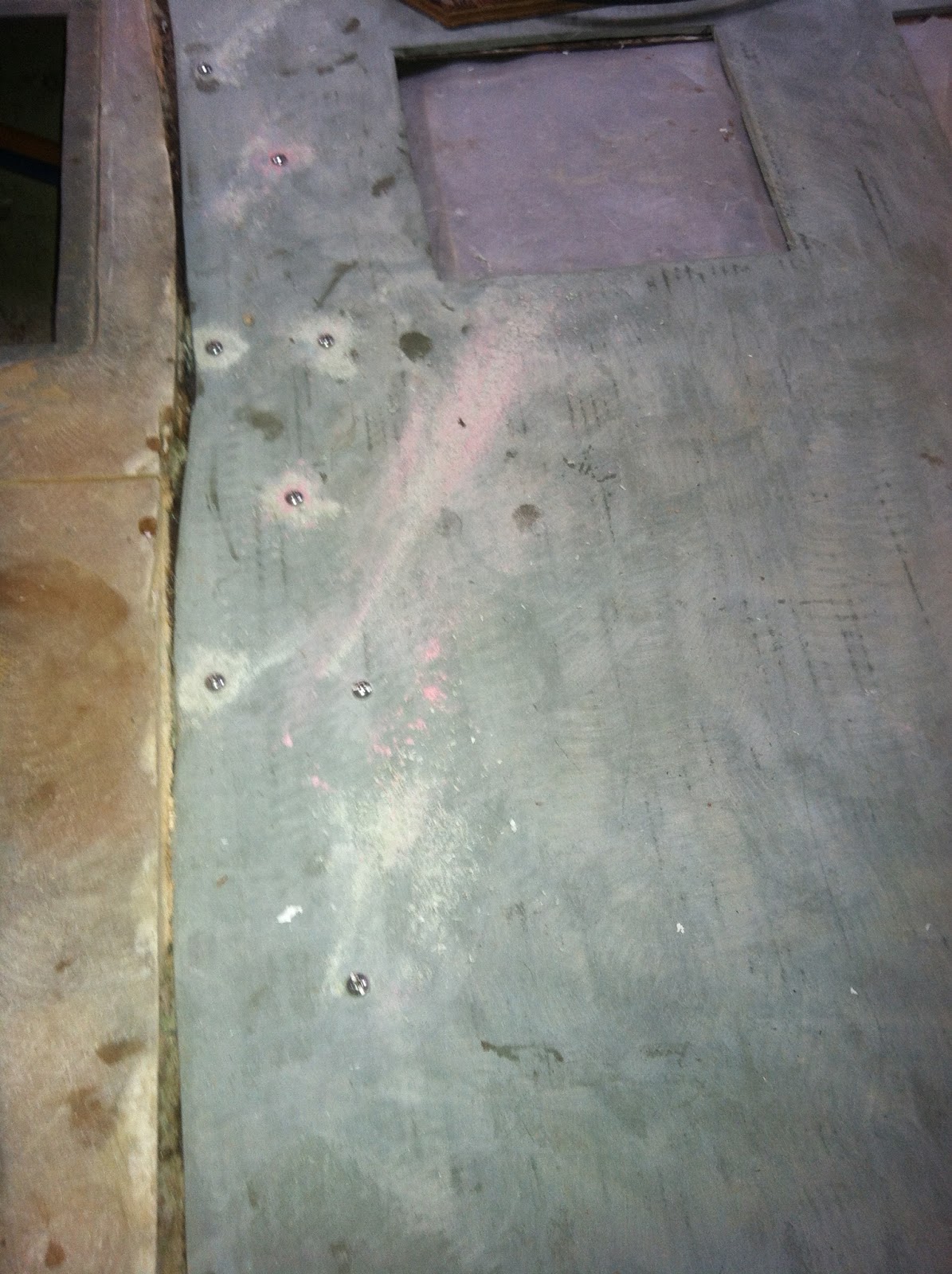
I put a bonding strip underneath here. It is made from 1/2" fiberglass panel. I screwed it to the 1/4" base panel to ensure a tight bond. All surfaces were scuffed up for better adhesion.
Two sections of the bulkhead in the forward salon were poorly bonded. During sonstruction, these areas were not cleaned and prepped before they were tabbed in. As a result the bottom areas where dirt collected, were poorly bonded. I ground these out--as shown here. Later photo's show the completed repair.

Same issue on starboard.

Port side repair. I used two layers of matt, two layers of roving, followed by one more layer of matt. Battery shown in this photo was one of three, in addition to other objects used as weights to bond the 14" floor panel to a remnant of the old panel on the starboard side.

Here is the port side layup on the bulkhead. You can another battery and a concrete block used as weights for the starboard side of the new floor.

Closeup of the port side layup.

Closeup of the starboard side layup. The string is being used to measure for the furniture being built for that side.

The next photo's are all of the bottom half of the aft bulkhead being installed. This is for a cofferdam to separate the rudder compartment from the middle of the boat. The below photo is the aft and port side of the bulkhead at the steering frame.

Aft view of the lower section of the bulkhead. Note there is a gap at the bottom which will need to be filled in one I install a piece of 1.5" stainless tubing. This will allow the aft bilge to drain though a hose and ball valve into the main bilge. That will eliminate the need for a bilge pump in this compartment.

Aft starboard view.

Another view from the aft.

The photo below shows one of the steering sheaves. It needs to be relocated on the right side of the frame. Likewise the port side sheave needs to move outboard also. The original steering was mounted forward in the cockpit and was relocated to a binnacle later. Whoever did this job, did not figure out the geometry properly as this limits the range of the rudder too much. I'll have move these sheaves, lengthen the rudder cables and build a frame to protect the sheaves for other items stored in this area.

Next task. Fabricating a mount for the autopilot hydraulic ram. I have prepped that area for fiberglassing and I have the materials ready to go.
